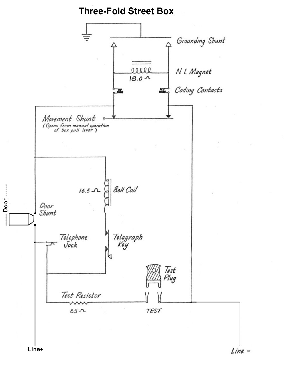
21+ Gamewell Wiring Diagram
Once power is on to the unit connect battery wiring harness Red Black -. Maximum size to house in cabinet is 12Ah.
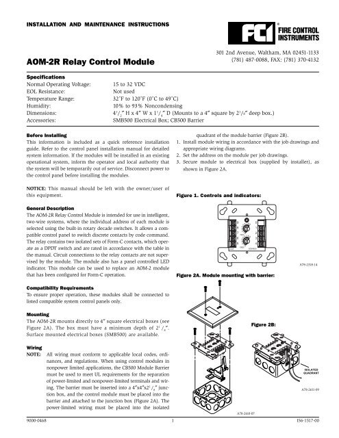
Aom 2rf Advancedalarmsystemsinc Com
Minimum battery size is 24V 7Ah.
. See NFPA 70 Article 760. Wiring diagrams continued ul listed control panel loop interface s sc - supply voltage to next sensor or return to control panel alarm contacts 100a 250vac nc alarm. Web The plectron was plugged into the wall and between the siren box and the plectron there was a timing switch that would allow the siren box to run for 2 minutes.
Web Use the conductor size and type required by local codes. Web trained installers and operators of the Gamewell-FCI 7100 Series Fire Alarm Control. Web Use the conductor size and type required by local codes.
All illustrations functional descriptions operating and installation procedures and other. Wiring resistance must not be more than that shown on the field wiring diagrams. Wiring resistance must not be more than that shown on the field wiring diagrams.
See NFPA 70 Article 760.

Hid Harness Circuit Demon
Napco Technical Library

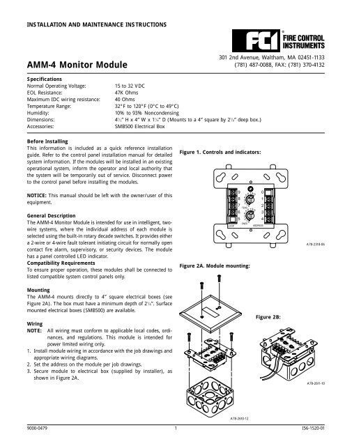
Gamewell Fci Amm 2f Addressable Monitor Module

Conventional Duct Smoke Detectors Gamewell Fci
New In Altium Designer Altium Designer 23 User Manual Documentation

Pid 95p Gamewell Point Identification Module Total Life Safety Solutions
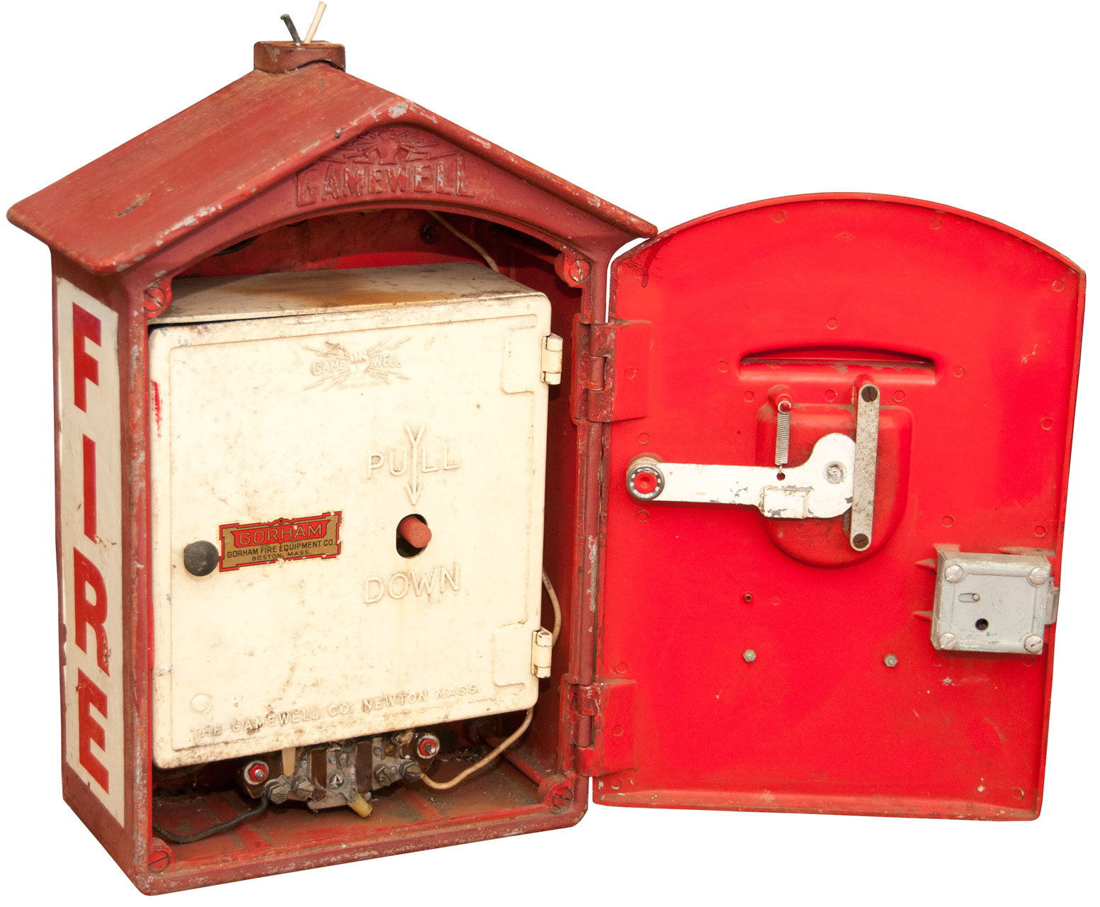
Gamewell Fire Alarm Box

Xp95 Series
Gamewell Fire Alarm Box

Gamewell Fci Gwsce 95 Or Sce 95 Signal Control Rybb Fire Alarm Parts Service Repairs
Amm 4f Advanced Alarm Systems

New Rauland Tcdpb2 Telecenter Dual Call Switch Fire Alarm Ebay
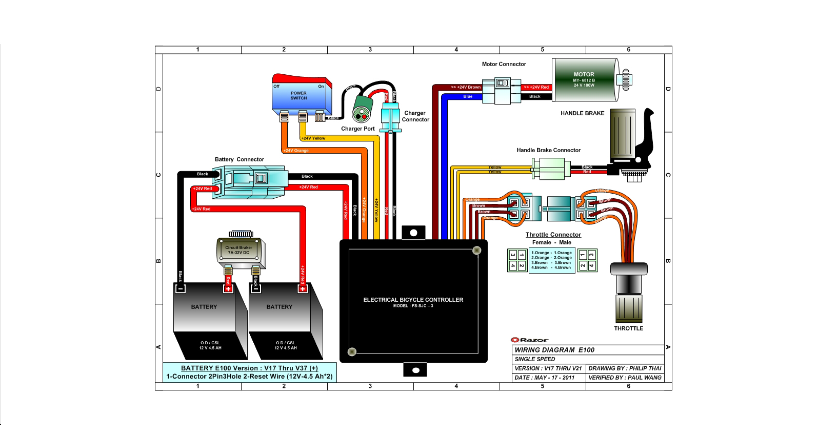
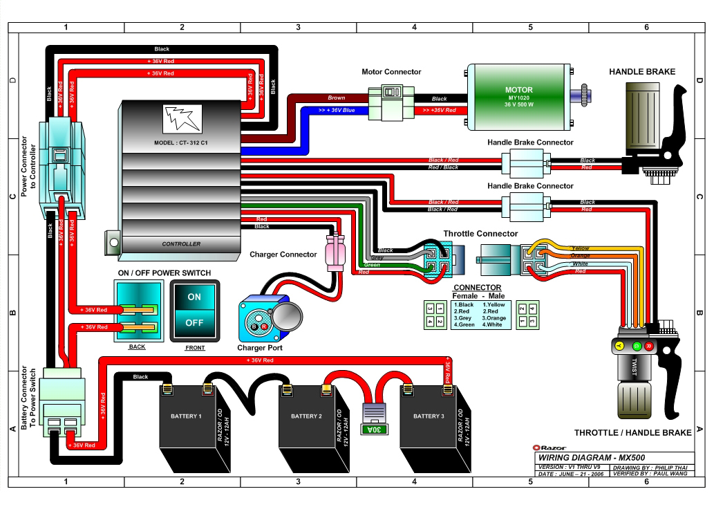
Razor Manuals

Dh100acdci Datasheet 3 4 Pages Systemsensor 4 Wire Ionization Duct Smoke Detector

Gamewell Fci Ms 7af Manual Pull Station Rybb Fire Alarm Parts Service Repairs
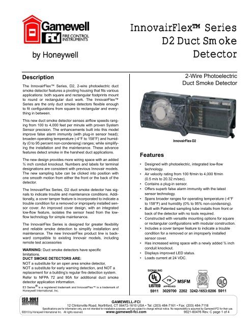
Innovairflexa Series D2 Duct Smoke Detector Gamewell Fci

Gamewell Fci E3 Loc Tel Wiring Diagram Fire Alarm Resources Free Fire Alarm Pdf Manuals Documents Installation Instructions And Technical Specifications